Wind Forces and Loads
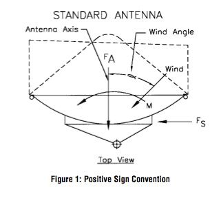
The wind’s direction and magnitude must be defined because it is a source of force on an antenna. This vectorial quantity is broken down into two forces and a moment as shown in Figure 1. FA , axial force, acts upon the axis of the antenna and passes through the vertex of the reflector. Fs , side force, acts perpendicular to the axis of the reflector and also passes through the vertex of the reflector. M, twisting moment, acts in the same plane as the horizontal axis of the reflector. Should the antenna mounting be such that there is an offset of the antenna axis from the mounting axis, additional moments are generated.
These are four factors that determine the magnitude of the three forces generated by the wind:
- Wind speed
- Antenna size
- Wind angle striking the antenna
- Antenna shape
The wind speed is usually considered as a maximum. The antenna size is defined. The wind angle is a constantly changing variable and is normally considered at that angle that generates the maximum loading.
To fully evaluate that variation of those forces, that are usually expressed in terms of coefficients:
C = Coefficient
A = Frontal area in square feet
V = Wind velocity in mph
D = Antenna diamter in feet
CA = FA/AV2
CS = FS/AV2
CM = M/DAV2
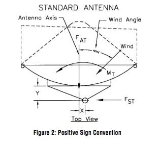
The actual force on the antenna mounting pipe must take into account the offset introduced by the antenna mount. These are shown in Figure 2.
X = Offset of the mounting pipe in feet (meters)
Y = Distance on the reflector axis from the reflector vertex to the center of the mounting pipe in feet (meters)
The total moment and forces exerted on the antenna mounting pipe can be determined by:
FA = FA
FST = FS
MT = M + FA(X) + FS(Y)
Using these coefficients, the following forces are generated for antennas at 125 mph (200 km/h). These are not the worst cases, but typical values.
Table 1
Typical coefficient value form solid antenna graphs based on RS-222
| Wind Angle | CA | CS | CM |
| 0° | 0.00397 | 0.00000 | 0.00000 |
| 45° | 0.00417 | 0.00012 | 0.000157 |
| 90° | 0.00003 | 0.00088 | 0.000336 |
| 135° | 0.00134 | 0.00117 | 0.000356 |
| 180° | 0.0027 | 0.00000 | 0.00000 |
Note: All antennas conform to specifications TIA/EIA-222-F and EIA-195-C.
Mark Parabolic Grids
| 350 -1000 MHz / 0 – 180° Angle / Without Ice | |||||||||
|---|---|---|---|---|---|---|---|---|---|
| Diameter | A | FA | FS | M | |||||
| ft. | m | sq. ft. | sq. m | lbs | N | lbs | N | ft-lbs | N-m |
| 3 | 0.9 | 1.32 | 0.12 | 83 | 369 | — | — | 33 | 45 |
| 4 | 1.2 | 4.55 | 0.41 | 284 | 1264 | — | — | 130 | 176 |
| 6 | 1.8 | 7.85 | 0.71 | 491 | 2185 | — | — | 286 | 388 |
| 8 | 2.4 | 11.92 | 1.07 | 745 | 3315 | — | — | 435 | 590 |
| 10 | 3 | 16.4 | 1.48 | 1025 | 4561 | — | — | 598 | 811 |
| 12 | 3.8 | 32.18 | 2.91 | 2011 | 8949 | — | — | 1173 | 1590 |
| 15 | 4.6 | 42 | 3.78 | 2625 | 11681 | — | — | 1531 | 2076 |
| 350 -1000 MHz / 90° Angle / Without Ice | |||||||||
| Diameter | A | FA | FS | M | |||||
| ft. | m | sq. ft. | sq. m | lbs | N | lbs | N | ft-lbs | N-m |
| 3 | 0.9 | 0.56 | 0.05 | — | — | 35 | 156 | 20 | 27 |
| 4 | 1.2 | 1.65 | 0.15 | — | — | 103 | 458 | 74 | 100 |
| 6 | 1.8 | 3.11 | 0.28 | — | — | 194 | 863 | 140 | 190 |
| 8 | 2.4 | 5.41 | 0.49 | — | — | 338 | 1504 | 243 | 329 |
| 10 | 3 | 7 | 0.63 | — | — | 438 | 1949 | 314 | 426 |
| 12 | 3.8 | 10.4 | 0.94 | — | — | 650 | 2893 | 596 | 808 |
| 15 | 4.6 | 21.75 | 1.96 | — | — | 1359 | 6048 | 1246 | 1689 |
| 350 -1000 MHz / 0 – 180° Angle / With 1/2″ Radial Ice | |||||||||
| Diameter | A | FA | FS | M | |||||
| ft. | m | sq. ft. | sq. m | lbs | N | lbs | N | ft-lbs | N-m |
| 3 | 0.9 | 3.66 | 0.33 | 229 | 1019 | — | — | 91 | 123 |
| 4 | 1.2 | 7.7 | 0.69 | 481 | 2140 | — | — | 221 | 230 |
| 6 | 1.8 | 14.33 | 1.3 | 896 | 3987 | — | — | 522 | 708 |
| 8 | 2.4 | 22.93 | 2.06 | 1433 | 6377 | — | — | 836 | 1133 |
| 10 | 3 | 33.07 | 2.98 | 2067 | 9198 | — | — | 1206 | 1635 |
| 12 | 3.8 | 52.57 | 4.73 | 3286 | 14616 | — | — | 1917 | 2599 |
| 15 | 4.6 | 83.66 | 7.53 | 5229 | 23269 | — | — | 3050 | 4135 |
| 350 -1000 MHz / 90° Angle / With 1/2″ Radial Ice | |||||||||
| Diameter | A | FA | FS | M | |||||
| ft. | m | sq. ft. | sq. m | lbs | N | lbs | N | ft-lbs | N-m |
| 3 | 0.9 | 1.33 | 0.12 | — | — | 83 | 369 | 48 | 65 |
| 4 | 1.2 | 1.92 | 0.17 | — | — | 120 | 534 | 86 | 117 |
| 6 | 1.8 | 3.11 | 0.28 | — | — | 194 | 863 | 140 | 190 |
| 8 | 2.4 | 6.4 | 0.58 | — | — | 400 | 1780 | 288 | 390 |
| 10 | 3 | 8.05 | 0.72 | — | — | 503 | 2238 | 362 | 491 |
| 12 | 3.8 | 12.71 | 1.14 | — | — | 761 | 3386 | 697 | 945 |
| 15 | 4.6 | 24.5 | 2.21 | — | — | 1531 | 6813 | 1404 | 1904 |
| 1000 -2700 MHz / 0 – 180° Angle / Without Ice | |||||||||
| Diameter | A | FA | FS | M | |||||
| ft. | m | sq. ft. | sq. m | lbs | N | lbs | N | ft-lbs | N-m |
| 3 | 0.9 | 2.24 | 0.2 | 140 | 623 | — | — | 55 | 75 |
| 4 | 1.2 | 6.32 | 0.57 | 395 | 1758 | — | — | 181 | 245 |
| 6 | 1.8 | 11.22 | 1.01 | 701 | 3119 | — | — | 409 | 555 |
| 8 | 2.4 | 19 | 1.71 | 1188 | 5287 | — | — | 693 | 940 |
| 10 | 3 | 27.43 | 2.47 | 1714 | 7627 | — | — | 1000 | 1356 |
| 12 | 3.8 | 46.87 | 4.22 | 2929 | 13034 | — | — | 1709 | 2317 |
| 15 | 4.6 | 79.72 | 7.17 | 4983 | 22174 | — | — | 2906 | 3940 |
| 1000 -2700 MHz / 90° Angle / Without Ice | |||||||||
| Diameter | A | FA | FS | M | |||||
| ft. | m | sq. ft. | sq. m | lbs | N | lbs | N | ft-lbs | N-m |
| 3 | 0.9 | 0.68 | 0.06 | — | — | 43 | 191 | 25 | 34 |
| 4 | 1.2 | 2.35 | 0.21 | — | — | 147 | 654 | 106 | 144 |
| 6 | 1.8 | 4.84 | 0.44 | — | — | 303 | 1348 | 218 | 296 |
| 8 | 2.4 | 8.39 | 0.76 | — | — | 524 | 2332 | 377 | 511 |
| 10 | 3 | 10.15 | 0.91 | — | — | 634 | 2821 | 459 | 622 |
| 12 | 3.8 | 15.71 | 1.41 | — | — | 982 | 4370 | 900 | 1220 |
| 15 | 4.6 | 30 | 2.7 | — | — | 1875 | 8344 | 1719 | 2331 |
| 1000 -2700 MHz / 0 – 180° Angle / With 1/2″ Radial Ice | |||||||||
| Diameter | A | FA | FS | M | |||||
| ft. | m | sq. ft. | sq. m | lbs | N | lbs | N | ft-lbs | N-m |
| 3 | 0.9 | 6.4 | 0.58 | 400 | 1780 | — | — | 158 | 214 |
| 4 | 1.2 | 11.82 | 1.06 | 739 | 3289 | — | — | 339 | 460 |
| 6 | 1.8 | 23 | 2.07 | 1438 | 6399 | — | — | 839 | 1138 |
| 8 | 2.4 | 39.43 | 3.55 | 2464 | 10965 | — | — | 1438 | 1950 |
| 10 | 3 | 59.83 | 5.38 | 3739 | 16639 | — | — | 2181 | 2960 |
| 12 | 3.8 | 90.57 | 8.15 | 5661 | 25191 | — | — | 3302 | 4477 |
| 15 | 4.6 | 146.6 | 13.19 | 9163 | 40775 | — | — | 5345 | 7247 |
| 1000 -2700 MHz / 90° Angle / With 1/2″ Radial Ice | |||||||||
| Diameter | A | FA | FS | M | |||||
| ft. | m | sq. ft. | sq. m | lbs | N | lbs | N | ft-lbs | N-m |
| 3 | 0.9 | 1.49 | 0.13 | — | — | 93 | 414 | 54 | 73 |
| 4 | 1.2 | 2.61 | 0.23 | — | — | 163 | 725 | 117 | 159 |
| 6 | 1.8 | 5.77 | 0.52 | — | — | 361 | 1606 | 259 | 351 |
| 8 | 2.4 | 10.2 | 0.92 | — | — | 638 | 2839 | 458 | 621 |
| 10 | 3 | 15.38 | 1.38 | — | — | 961 | 4276 | 691 | 937 |
| 12 | 3.8 | 22.33 | 2.01 | — | — | 1396 | 6212 | 1279 | 1734 |
| 15 | 4.6 | 35.98 | 3.24 | — | — | 2249 | 10008 | 2061 | 2794 |